Käesolev juhend on tõlgitud lehelt https://www.arduino.cc/en/Tutorial/HelloWorld
Kood kirjutab ekraanile teksti ja loeb sekundeid alates sisselülitamise hetkest.
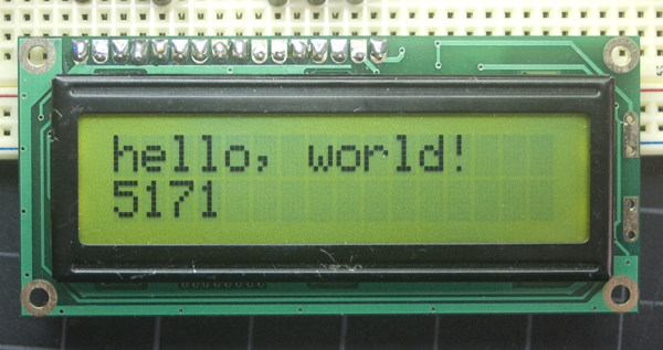
Kood kirjutab ekraanile teksti ja loeb sekundeid alates sisselülitamise hetkest.
RS pin - valib kuhu LCD mälus andmed kirjutatakse.
R/W pin - valib kirjutamise või lugemise. Kui on lubatud, siis saab kirjutada.
8 andme pinni (D0 -D7). Pinnide seisund (high või low) võimaldab andmeid lugeda või kirjutada.
Ekraani kontrastsuse pin Vo, toide (+5V ja Gnd) ja LED taustavalgus (Bklt+ ja BKlt-).
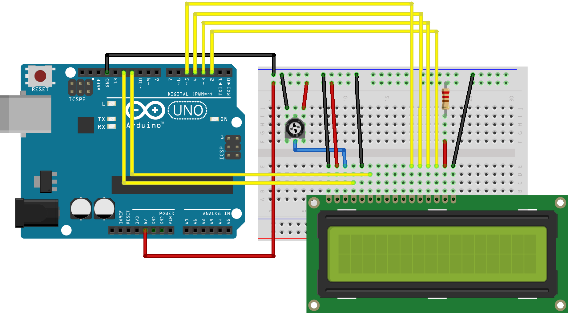
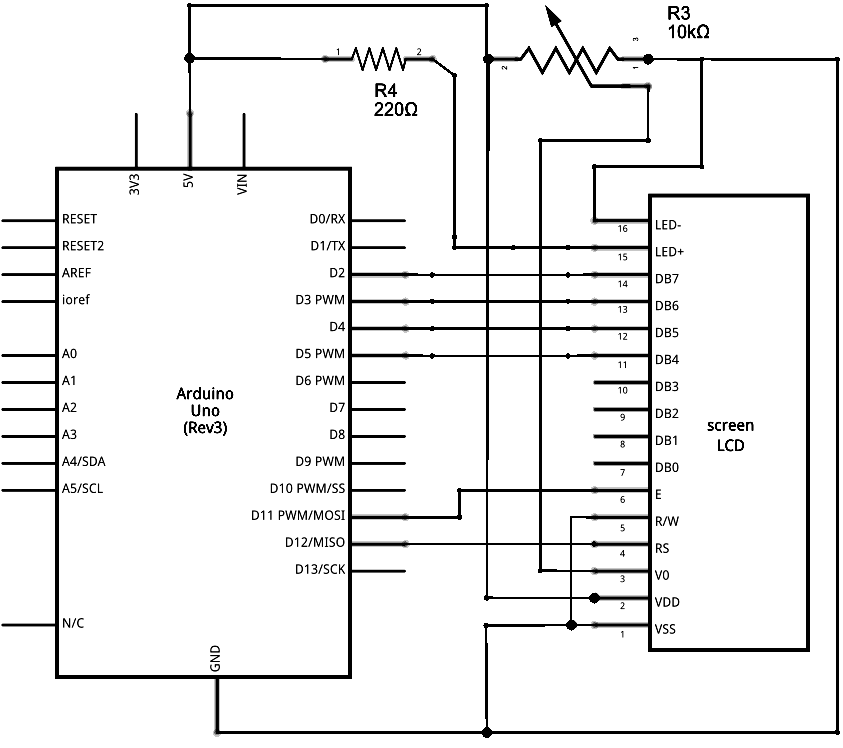
Skeem
- LCD RS pin ühenda digital pin 12
- LCD Enable pin ühenda digital pin 11
- LCD D4 pin ühenda digital pin 5
- LCD D5 pin ühenda digital pin 4
- LCD D6 pin ühenda digital pin 3
- LCD D7 pin ühenda digital pin 2
Lisaks ühenda 10k potensiomeeter +5V ja GND. 220 oomine takisti ühendatakse taustavalguse tarbeks pinnidele 15 ja 16 LCD ekraanil.
Kood
/*
LiquidCrystal Library - Hello World
Demonstrates the use a 16x2 LCD display. The LiquidCrystal
library works with all LCD displays that are compatible with the
Hitachi HD44780 driver. There are many of them out there, and you
can usually tell them by the 16-pin interface.
This sketch prints "Hello World!" to the LCD
and shows the time.
The circuit:
* LCD RS pin to digital pin 12
* LCD Enable pin to digital pin 11
* LCD D4 pin to digital pin 5
* LCD D5 pin to digital pin 4
* LCD D6 pin to digital pin 3
* LCD D7 pin to digital pin 2
* LCD R/W pin to ground
* LCD VSS pin to ground
* LCD VCC pin to 5V
* 10K resistor:
* ends to +5V and ground
* wiper to LCD VO pin (pin 3)
Library originally added 18 Apr 2008
by David A. Mellis
library modified 5 Jul 2009
by Limor Fried (http://www.ladyada.net)
example added 9 Jul 2009
by Tom Igoe
modified 22 Nov 2010
by Tom Igoe
This example code is in the public domain.
http://www.arduino.cc/en/Tutorial/LiquidCrystal
*/
// include the library code:
#include <LiquidCrystal.h>
// initialize the library with the numbers of the interface pins
LiquidCrystal lcd(12, 11, 5, 4, 3, 2);
void setup() {
// set up the LCD's number of columns and rows:
lcd.begin(16, 2);
// Print a message to the LCD.
lcd.print("hello, world!");
}
void loop() {
// set the cursor to column 0, line 1
// (note: line 1 is the second row, since counting begins with 0):
lcd.setCursor(0, 1);
// print the number of seconds since reset:
lcd.print(millis() / 1000);
}
